

Views: 0 Author: Site Editor Publish Time: 2026-08-05 Origin: Site


Discovering that fabricated parts do not align during the final production stage creates immediate financial and operational headaches. Production bottlenecks form rapidly. Scrapped materials pile up on the shop floor. Emergency rework destroys project timelines and frustrates engineering teams. This disconnect between theoretical CAD models and physical manufacturing realities happens because minor deviations in cutting, bending, or welding compound across complex assemblies. A digital model assumes perfect geometry, but the physical world introduces material inconsistencies, thermal distortion, and tooling wear.
Resolving these fitment issues requires a dual approach. You must apply rigorous Design for Manufacturability (DFM) at the engineering level to eliminate unnecessary geometric risks. Simultaneously, you need to partner with a fabricator capable of executing tight tolerances consistently. Relying on brute force to assemble misaligned components compromises structural integrity and introduces residual stress. This guide breaks down the root causes of fitment failures and provides actionable engineering strategies to ensure your components mate perfectly on the first try.
Tolerance Stack-Up is the Primary Culprit: Small, acceptable deviations in individual parts compound across an assembly, leading to catastrophic misalignment if not managed through proper datum structuring.
Process Heat Causes Unpredictable Distortion: Secondary operations like welding and hot-dip galvanizing introduce thermal stress, warping parts out of specification.
Smart Dimensioning Prevents Assembly Friction: Utilizing slots instead of tight round holes, keeping critical features on a single plane, and dimensioning from a single primary datum significantly increases fitment success rates.
Fabricator Capabilities Dictate Assembly Success: Selecting a partner with advanced precision sheet metal fabrication equipment, rigorous machine maintenance schedules, and strict First Article Inspection (FAI) protocols mitigates the risk of receiving out-of-spec parts.
Tolerance stack-up occurs when the dimensional variations of individual components accumulate across an entire assembly. Each fabricated part carries a specific tolerance range. When these parts mate, their individual deviations aggregate. Even if every single component passes inspection and falls within acceptable limits, the combined variance can easily exceed the total allowable assembly tolerance. This results in holes that do not align, flanges that overlap, and enclosures that refuse to close.
Consider a chassis with four bends between two mounting holes. If the press brake holds a +/- 0.010-inch tolerance per bend, four bends mean a potential +/- 0.040-inch deviation. If the mating part also carries a +/- 0.010-inch tolerance, the total worst-case mismatch reaches 0.050 inches. A standard 1/4-20 bolt in a 0.281-inch clearance hole only provides 0.031 inches of float. The bolt will not fit. You can audit your designs for stack-up risks using a straightforward process:
Identify the primary datum surface on the main chassis.
Trace the dimensional path from the datum to the first mating feature.
Record the maximum allowable material condition for each intermediate bend or cut.
Sum the individual tolerances to find the worst-case deviation.
Compare the total deviation against the clearance of the mating fastener.
Engineers often fail to distinguish between blanket tolerances and critical-to-function tolerances. Blanket tolerances apply a uniform acceptable variance across an entire drawing. This approach ignores the reality that certain mating surfaces require much tighter control than non-functional exterior edges. Failing to isolate and control these critical dimensions guarantees fitment issues during sheet metal assembly.
Dimensioning holes or features from multiple, unrelated edges creates a chaotic manufacturing environment. When a drawing references different edges for different hole locations, it forces the machine operator to constantly change the physical reference point during fabrication. This introduces new fixturing errors at every step. Treating every edge as an independent baseline rather than establishing a rigid geometric hierarchy guarantees failure.
A lack of a clear primary datum leads to inconsistent fixturing. The primary datum serves as the absolute anchor for the part. Without it, the fabricator cannot reliably orient the metal in the CNC press brake or laser cutter. Every subsequent bend or cut inherits the orientation error of the previous step. Dimensioning from a single primary datum ensures that all critical features remain locked in relation to one another. For example, laser-cut holes are processed in the same setup, meaning hole-to-hole tolerance remains incredibly tight. Dimensioning from a sheared edge introduces the shear's wider tolerance into your hole locations.
Transforming a 3D model into a 2D flat pattern requires precise mathematical calculations. Incorrect K-factor calculations lead directly to flat patterns that are either too long or too short. The K-factor represents the location of the neutral axis within the material during a bend. If you guess this value or use a generic software default, the resulting flat pattern will not accurately reflect the physical stretching of the metal.
Variations in physical tooling heavily influence the final dimensions of sheet metal bending parts. The width of the V-die and the radius of the punch dictate the actual inner radius of the bend. If the CAD model assumes a 0.060-inch bend radius, but the fabricator uses a 0.500-inch V-die based on shop floor availability, the bend deduction changes completely. This mismatch alters the overall flange length, pushing mating holes entirely out of position.
Localized heat input from welding processes completely alters the dimensional stability of metal. TIG, MIG, and laser welding introduce extreme thermal gradients. The metal expands rapidly at the weld pool and then contracts as it cools. This localized shrinkage causes warping, bowing, and severe angular distortion. When executing a complex sheet metal welding assembly, this distortion pulls previously aligned features entirely out of specification.
Welding Process | Heat Input Level | Distortion Risk | Best Application for Fitment |
|---|---|---|---|
TIG (GTAW) | High | Severe | Thin gauge cosmetic joints requiring blending |
MIG (GMAW) | Medium | Moderate | Structural frames and heavy brackets |
Laser Welding | Low | Minimal | High-precision enclosures and tight tolerance parts |
Spot Welding | Very Low | None | Overlapping flanges with hidden joints |
Secondary finishing processes present similar risks. Hot-dip galvanizing requires submerging parts in a bath of molten zinc at roughly 830°F. This extreme heat relieves internal stresses built up during the rolling and bending phases at the steel mill. For thin-gauge materials, this sudden stress relief manifests as violent twisting and severe hole misalignment. Parts that fit perfectly before galvanizing often require aggressive mechanical straightening afterward just to assemble.
Sheet metal is not a perfectly uniform material. Inconsistencies in material thickness and yield strength occur naturally across different mill batches. A batch of A36 steel might run at the upper limit of its thickness tolerance, while the next batch runs at the lower limit. These variations directly affect how the material reacts under the press brake, causing unpredictable bend angles even when using identical machine settings.
Springback complicates this further. When metal bends, it naturally attempts to return to its original flat state due to elastic recovery. Fabricators must over-bend the material to achieve the target angle. For example, bending 304 stainless steel requires significantly more over-bending than mild steel. Failure to calculate and execute this over-bend accurately results in parts that do not sit flush. Additionally, material grain direction impacts bend consistency. Bending parallel to the grain increases the risk of fracturing and alters the springback characteristics, weakening the structural integrity of the final component. Operators must nest parts on the laser bed so that critical bends run perpendicular to the material grain.
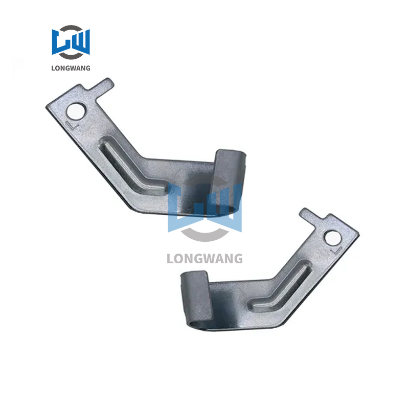
Isolating part design from the final assembly environment guarantees fitment friction. Utilizing CAD assembly environments during the early concept stage allows engineers to visualize and test fitment before detailing individual components. This top-down approach forces the designer to consider how parts interact physically in three-dimensional space. Skeletal modeling techniques allow you to drive all part dimensions from a single master sketch. If you change the overall width of the assembly, all mating parts update automatically.
Designing sheet metal assembly parts in-context helps identify spatial conflicts and tolerance overlaps early in the engineering phase. Instead of discovering a collision on the shop floor, engineers can manipulate mating surfaces digitally. This proactive modeling highlights areas where material thickness variations or bend radii might interfere with adjacent components, allowing for immediate geometric corrections before cutting any metal.
Every bend introduces a new variable into the tolerance equation. Designing parts so that critical mounting holes and mating features reside on the same flat surface eliminates these variables. When you keep functional features on a single plane, you rely solely on the precision of the laser or punch press, which is inherently more accurate than the press brake.
Avoiding the need to span critical dimensions across multiple bends protects the assembly from compounding errors. If a mounting bracket requires two holes separated by three bends, the distance between those holes absorbs the tolerance deviation of all three bending operations. Flattening the design to keep those holes on one continuous surface ensures they remain exactly where the CAD model dictates. We see this often on the shop floor with NEMA enclosure doors; keeping the hinge cutouts and lock holes on the same unbent face guarantees perfect alignment.
Tight round holes offer zero margin for error. Designing mating parts with exact-match round holes assumes a perfect manufacturing environment that does not exist. When tolerances stack up, even a fraction of a millimeter of deviation prevents a fastener from passing through both parts cleanly. This forces assemblers to drill out holes manually, generating metal shavings and compromising the powder-coated finish.
Replacing round holes with slots in one of the mating parts absorbs tolerance variations effortlessly. Slots provide a designated float allowance. For example, a 1/4-inch bolt requires a 0.281-inch round hole for standard clearance. If you use a slot, size it to 0.281 inches wide by 0.375 inches long, oriented in the direction of the expected tolerance stack-up. They allow the parts to slide into alignment without forcing the metal or stressing the fasteners. This simple geometric change transforms a rigid, failure-prone design into a self-fixturing assembly that goes together smoothly on the production line.
Keeping bends oriented in the same direction throughout an assembly helps parts behave predictably. When a fabricator can process a part without constantly flipping it over on the press brake, they reduce handling errors and maintain a consistent reference plane. This operational consistency translates directly into tighter dimensional control and faster production times.
Bend relief cuts are non-negotiable for precise fitment. When a bend terminates near a flat edge or another flange, the material stretches and tears. This tearing creates jagged burrs and localized deformation that interfere with mating surfaces. Adding proper bend relief cuts gives the material room to deform cleanly. A standard rule of thumb dictates that the relief width should equal the material thickness, and the depth should equal the material thickness plus the bend radius. This ensures the adjacent surfaces remain perfectly flat.
Relying entirely on complex welding fixtures to hold parts together introduces unnecessary risk and labor. Standardizing hardware reduces this reliance. Self-clinching fasteners, such as PEM nuts and standoffs, provide precise, threaded mounting points that press directly into the flat sheet metal before bending. You punch a precise hole on the laser, and the hardware insertion press locks the nut into place by displacing metal into the fastener's undercut. This guarantees location accuracy based on the initial laser cut.
Tab-and-slot designs offer another highly effective fastening method. By designing tabs on one part that interlock with slots on the mating part, the assembly effectively jigs itself. This self-locating geometry ensures parts can only fit together in the correct orientation, eliminating guesswork and drastically reducing the time required for final assembly.
The equipment sitting on a fabricator's shop floor dictates the quality of your parts. Evaluating a partner requires looking beyond their marketing materials and examining their actual hardware. CNC press brakes equipped with active angle measurement systems adjust in real-time to material thickness variations, ensuring exact bend angles. High-wattage fiber lasers provide clean edges with minimal heat-affected zones, preventing localized warping.
Poor machine maintenance directly contributes to inconsistent bend angles and fitment failures. Worn V-dies create uneven bend radii. Uncalibrated backgauges result in flanges that are consistently out of tolerance. A fabricator executing precision sheet metal fabrication must utilize CNC crowning systems on their press brakes. Crowning pushes up on the center of the lower bed to counteract the natural deflection of the ram under tonnage. Without it, long bends will measure 90 degrees on the ends and 92 degrees in the middle, a defect known as canoeing. Modern, well-maintained tooling prevents these micro-inconsistencies.
A robust inspection framework separates reliable fabricators from high-risk vendors. Standard inspection lenses for high-reliability parts must include Coordinate Measuring Machines (CMM), 3D laser scanning, and automated optical inspection. A CMM touches the part with a ruby probe to verify complex geometries against the original CAD model. Virtek laser scanners compare the flat pattern directly to the DXF file in seconds, catching deviations that manual calipers miss.
The method of measurement matters just as much as the tool. Fabricators must understand the difference between measuring parts in a constrained state versus a free state. Sheet metal naturally flexes. A part that measures out of tolerance while resting freely on a table might pull perfectly into alignment once bolted to a rigid frame. A competent partner establishes inspection criteria that reflect the actual assembly conditions.
Engineers frequently face the trade-off between designing fully custom enclosures and adapting off-the-shelf components. Standardized solutions appear cheaper initially but often require heavy modification, adapter plates, and compromised layouts to fit specific internal hardware. These workarounds introduce new tolerance stack-up risks and aesthetic flaws.
Investing in custom sheet metal fabrication eliminates these compromises. When executed by a specialized partner, custom designs consolidate parts, integrate self-fixturing features, and optimize the exact footprint required. While the upfront engineering time is higher, custom fabrication ultimately reduces assembly labor, eliminates excess hardware costs, and ensures a superior final fit.
Moving directly from a CAD screen to high-volume production without physical validation is a massive operational risk. Theoretical models cannot account for the specific tooling dynamics of the chosen fabricator. Skipping the prototyping phase almost guarantees that thousands of out-of-spec parts will arrive at your loading dock, halting production entirely.
Implement a strict First Article Inspection (FAI) process to verify manufacturing intent. The FAI requires the fabricator to produce a small initial run of parts using the exact production tooling and processes intended for the full run. You measure every single dimension on the drawing for the first part and record the actual values. This allows engineers to physically verify bend deductions and test the assembly fitment. You adjust the press brake programs based on this data before running the remaining parts.
Tolerance communication dictates manufacturing costs and assembly success. Over-tolerancing applies extremely tight constraints to non-critical features. This drives up costs unnecessarily by forcing the fabricator to use slower, high-precision methods for every edge. Under-tolerancing leaves critical mating surfaces vulnerable to standard shop deviations, resulting in assembly failure.
Feature Type | Standard Tolerance | Precision Tolerance | Cost Impact |
|---|---|---|---|
Laser Cut Edges | +/- 0.010" | +/- 0.005" | Low |
Hole Diameters | +/- 0.005" | +/- 0.002" | Low |
Bend to Edge | +/- 0.015" | +/- 0.008" | High |
Bend to Bend | +/- 0.020" | +/- 0.010" | Very High |
The most effective mitigation strategy is conducting collaborative DFM reviews. Before cutting any metal, the OEM engineering team must sit down with the fabricator's manufacturing engineers. This review aligns the CAD model's theoretical tolerances with the fabricator's actual machine capabilities, ensuring that critical dimensions are protected without inflating the overall production budget.
Sheet metal assembly failures are rarely a single point of failure. They are the inevitable result of compounded tolerances, unmitigated thermal stress, poor design practices, and misaligned manufacturing capabilities. When engineers treat sheet metal as a perfect geometric plane rather than a dynamic material, fitment friction is guaranteed. Solving these issues requires moving beyond basic CAD drafting and embracing comprehensive Design for Manufacturability.
Selecting the right fabrication partner forms the foundation of assembly success. Your shortlisting logic must prioritize transparent communication regarding tooling constraints, rigorous First Article Inspection protocols, proactive machine maintenance, and advanced CNC capabilities. A fabricator who challenges your drawings and suggests DFM improvements is a partner worth keeping.
Audit your current failing assemblies to identify improper datum structures and eliminate tolerance stack-up loops.
Replace rigid round mounting holes with slotted designs to provide necessary float allowance during final assembly.
Consolidate critical mating features onto single flat planes to remove bending variables from the tolerance equation.
Submit your updated CAD files to a qualified fabrication partner for a comprehensive DFM review and tooling alignment check.
A: Localized heat input from welding causes rapid thermal expansion in the metal. As the weld pool cools, the material contracts. This uneven heating and cooling cycle creates severe residual stress, which pulls the metal out of its original shape, resulting in warping, bowing, and angular distortion.
A: Identify the primary datum first. List all dimensional variables and individual part tolerances between the mating features. Calculate the worst-case maximum and minimum material conditions by adding the maximum allowable deviations together. If this total exceeds the acceptable assembly clearance, you must tighten individual tolerances or redesign the joint.
A: Bend allowance is the arc length of the neutral axis through the bend. Bend deduction is the specific amount of material removed from the total flat length of the sheet to achieve the desired formed dimension. Accurate bend deductions rely on the exact tooling used during fabrication.
A: Yes. The extreme heat of the molten zinc bath relieves internal stresses built up during the rolling and bending processes. In thin-gauge sheet metal, this rapid stress relief causes severe warping, twisting, and hole misalignment, often requiring mechanical straightening after the coating cools.
A: Slots provide a necessary float allowance to accommodate standard manufacturing tolerances. Because sheet metal parts naturally deviate slightly during bending, slots ensure that fasteners can pass through mating components smoothly without requiring forced alignment, drilling, or manual rework on the assembly line.
A: Bending parallel to the material's grain direction increases the risk of cracking and fracturing along the bend line. It also alters the springback characteristics unpredictably. Bending perpendicular to the grain ensures stronger structural integrity and allows for more precise, repeatable bend angles.
A: Using top-down, in-context assembly modeling during the concept phase allows engineers to visualize spatial relationships in 3D. This highlights tolerance overlaps, hardware collisions, and spatial conflicts before finalizing individual part drawings, ensuring that components will physically mate on the shop floor.


