

Views: 0 Author: Site Editor Publish Time: 2026-08-12 Origin: Site


In complex assemblies, a dimensional deviation of a fraction of a millimeter in a single bent component causes cascading failures. You get assembly interference, compromised structural integrity, and production delays. Engineers and procurement teams frequently encounter dimensional drift between the CAD model and the physical part. Understanding the root causes of these variations—ranging from material physics to machine calibration—prevents rework and controls manufacturing timelines. Achieving precision requires strict Design for Manufacturability (DFM) standards, accurate material selection, and partnering with a capable manufacturer. This guide breaks down the variables that alter bending dimensions. We provide a framework for ensuring repeatable accuracy across common components like brackets, enclosures, and structural panels. By mastering these variables, engineering teams can design robust components that transition seamlessly from digital models to physical reality on the shop floor.
Springback is Inevitable: All metals experience elastic recovery after bending; accurate calculation of the K-factor and bend allowance is non-negotiable for dimensional accuracy.
Material Inconsistencies Drive Variation: Standard gauge thickness variations, differing grain directions, and specific material types directly impact the final bend angle and radius.
DFM Dictates Feasibility: Designing with appropriate bend radii, sufficient flange heights, proper feature spacing, and logical bending sequences prevents mechanical distortion during the forming process.
Manufacturer Capability Matters: Consistently holding a tight sheet metal fabrication tolerance requires advanced press brake technology, well-maintained tooling, and rigorous First Article Inspection (FAI) protocols.
Before evaluating vendor capabilities, buyers must understand the physical limitations of metal deformation to set realistic success criteria for their custom bending parts. Dimensional shifts are rarely random. They result from applied physics, material properties, and the mechanical forces exerted during the forming process. Acknowledging these physical realities helps you engineer components that can be manufactured with repeatable precision.
Sheet metal bending is a forming process where force is applied to a metal sheet using a press brake and tooling. This pushes the material past its yield point to cause permanent plastic deformation. During this process, the material undergoes severe internal stress. The inner surface of the bend compresses, while the outer surface stretches under tension. This opposing force dynamic causes the neutral axis—the theoretical plane within the material that experiences zero stress—to shift inward toward the inner radius.
The exact location of this neutral axis is defined by the K-factor. This mathematical value dictates the flat pattern layout. If the K-factor is miscalculated, the flat blank will be cut to the wrong size. That guarantees the final bent dimensions will fail to meet the required specifications. Accurate deformation modeling requires precise knowledge of the material's behavior under load.
To control plastic deformation on the shop floor, operators follow a strict sequence of operations:
Verify the material thickness using digital calipers to confirm it falls within the expected gauge tolerance.
Select the appropriate V-die opening, typically eight times the material thickness for standard air bending.
Align the punch and die to ensure perfectly parallel engagement across the entire bed length.
Perform a test bend on a scrap piece from the exact same material lot to measure the actual neutral axis shift.
Springback is the natural tendency of sheet metal to partially return to its original flat shape after the bending force is removed. When the press brake releases its pressure, the elastic strain within the material relaxes. This causes the bend angle to open up slightly and the bend radius to expand. Elastic recovery happens in all metal forming operations.
The severity of springback depends on the material's yield strength, the specific alloy type, and the chosen bend radius. High-strength materials exhibit significantly more springback than softer materials. A larger bend radius relative to the material thickness generates a higher degree of elastic recovery. Operators compensate by overbending the material. They push it past the target angle, relying on predictive software and test bends to ensure the metal relaxes exactly into the desired final dimension.
Material Type | Yield Strength (Approx.) | Springback Severity | Typical Overbend Required |
|---|---|---|---|
5052-H32 Aluminum | 28,000 psi | Low | 0.5° - 1.5° |
1018 Cold Rolled Steel | 54,000 psi | Moderate | 1.0° - 2.5° |
304 Stainless Steel | 42,000 psi (Work Hardens) | High | 2.0° - 5.0° |
High-Strength Low-Alloy (HSLA) | 80,000+ psi | Very High | 4.0° - 8.0° |
The manufacturing process of raw sheet metal involves rolling large ingots through heavy rollers. This elongates the crystalline structure of the metal and creates a distinct grain direction. This microscopic alignment behaves similarly to the grain found in wood. The orientation of the bend line relative to this grain direction heavily influences both the structural integrity and the dimensional accuracy of the final part.
Bending parallel to the grain separates the elongated fibers. This increases the risk of fracturing, cracking, and unpredictable dimensional shifting along the outer tension line. Bending perpendicular to the grain pushes against the fibers, resulting in cleaner, stronger, and much more predictable bends. When nesting flat patterns onto a raw sheet for laser cutting, engineers face a trade-off. They must balance maximizing material yield to reduce waste against optimizing the layout to ensure all primary bends run perpendicular to the grain.
Selecting the right material grade and understanding its inherent variables controls the final dimensions of the component. Even with perfect machinery, inconsistent raw materials yield inconsistent parts. Maintaining a strict sheet metal fabrication tolerance requires a deep understanding of how commercial material variations affect the forming process.
Commercial sheet metal is not manufactured to absolute dimensions. It is produced within a standard tolerance range for thickness. A standard piece of 11-gauge steel might measure exactly 0.1196 inches, but the mill tolerance allows it to vary by several thousandths of an inch across the same sheet or between different batches. These microscopic variations have a macroscopic impact on the bending process.
Press brake tooling relies on precise depth calculations to achieve specific angles. An unexpected increase in material thickness causes the punch to drive deeper into the V-die relative to the material volume. This results in an overbent angle. Thinner material will underbend. Thickness variations alter the inside bend radius and shift the neutral axis, directly changing the overall flange lengths and hole-to-bend dimensions.
Different material types dictate baseline bending behavior and require distinct tooling choices. Forming 5052 Aluminum requires different tonnage, punch radii, and die openings compared to forming 304 Stainless Steel. Stainless steel work-hardens rapidly during deformation. It requires significantly more force and robust tooling to achieve the same bend angle as a softer alloy.
Variations in material hardness within the same batch affect the amount of force required to bend the metal. If a specific section of a sheet is slightly harder due to localized cooling rates at the mill, it resists deformation more strongly and exhibits higher springback. Inconsistent hardness leads to variable angles along a single bend line. Operators must make real-time machine adjustments or utilize active angle measurement systems to maintain the required tolerance.
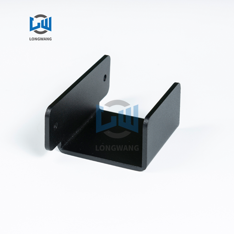
Assessing how closely a design adheres to standard DFM principles determines whether tight tolerances are physically achievable or mathematically impossible. Many dimensional errors originate in the CAD software rather than on the shop floor. Designing robust sheet metal bending parts requires strict adherence to geometric rules that respect the physics of metal deformation.
The baseline rule of sheet metal design is that the inside bend radius should generally be equal to or greater than the material thickness. Thicker materials inherently demand larger bend radii to accommodate the increased volume of metal being displaced during the bend. Pushing the limits of this ratio invites severe manufacturing defects.
Specifying a bend radius that is too small for the material thickness causes extreme stress on the outer tension line. This leads to material fractures, localized thinning, and a phenomenon known as necking, where the metal weakens and distorts. When the material fractures or thins unpredictably, the neutral axis shifts erratically. This destroys any chance of holding accurate flat pattern calculations or final part dimensions.
Material Thickness (T) | Recommended Minimum Inside Bend Radius | Risk of Fracture if Undersized |
|---|---|---|
0.030" - 0.060" | 1.0 x T | Low to Moderate |
0.061" - 0.125" | 1.5 x T | Moderate |
0.126" - 0.250" | 2.0 x T | High |
> 0.250" | 2.5 x T to 3.0 x T | Very High |
A flange must have sufficient length to bridge the V-die during the forming process. The minimum flange length requirement is typically calculated as four times the material thickness plus the bend radius. This ensures the material remains fully supported by the die shoulders as the punch descends.
When bending heights are designed too low, the sheet metal lacks the necessary surface area to rest securely on the tooling. As the punch applies pressure, the short flange slips off the die shoulder and gets dragged down into the V-die. This results in severe deformation, twisted edges, and a complete loss of dimensional control. If a short flange is absolutely necessary for the assembly, it requires custom tooling or secondary machining operations, significantly increasing production time.
Placing holes, slots, or intricate cutouts too close to the bend line is a frequent cause of dimensional failure. The area immediately surrounding the bend line undergoes massive stress and strain during plastic deformation. If a void exists within this deformation zone, the surrounding metal will flow into the path of least resistance.
This dynamic causes round holes to stretch into ovals, slots to warp, and thin webs of material to tear completely. Once a feature distorts, its dimensional location relative to the rest of the part is lost. To mitigate this, engineers must place features outside the minimum distance zone—typically 2.5 to 3 times the material thickness away from the bend line—or design relief cuts that isolate the feature from the stress of the bend.
Designing bends that intersect beveled, chamfered, or angled edges introduces severe instability into the forming process. Press brake tooling is designed to apply uniform pressure across a consistent material profile. When the material profile changes along the bend line, the resistance to the punch becomes unbalanced.
This uneven material distribution causes the part to twist and skew as the punch descends. The side with more material resists the bend, while the side with less material yields faster. This differential yielding ruins the dimensional accuracy of the part, making it impossible to achieve a straight, parallel bend. Designs must ensure that the bend line passes through a uniform cross-section of material.
Designing parts without considering the order of operations leads to inevitable tooling interference. A complex enclosure with multiple internal flanges must be bent in a specific sequence. If the design does not allow for a logical progression of bends, the part cannot be manufactured as drawn.
Incorrect bending sequences cause earlier bends to block or collide with the press brake tooling during subsequent operations. When a collision occurs, operators are forced to use non-standard setups, segmented tooling, or manual workarounds that compromise the rigidity of the setup. This lack of stability directly translates to angular variations and dimensional drift across the finished component.
The physical equipment dictates the baseline accuracy and repeatability of the production run. Achieving precision sheet metal bending is impossible on degraded machinery or with improper tooling setups. The interaction between the press brake, the dies, and the metal is the final frontier of dimensional control.
The chosen bending method fundamentally alters how tolerances are achieved and maintained. The three primary methods are air bending, bottoming, and coining, each with distinct mechanical profiles.
Air bending is the most common method. The punch presses the material into the V-die without forcing it all the way to the bottom. The inside radius is determined by the die opening rather than the punch tip. While highly flexible and requiring less tonnage, air bending relies heavily on the accuracy of the press brake's ram depth and the consistency of the material thickness.
Bottoming and coining force the material fully into the die, stamping the exact shape of the tooling into the metal. This method provides higher precision and significantly reduces springback because the material is structurally set under extreme pressure. It requires massive tonnage, highly specific tooling for every angle and radius, and causes faster machine wear.
The mechanical health of the press brake is a major variable. Machine age, hydraulic fluid consistency, and the accuracy of the CNC control system all impact dimensional repeatability. As a press brake applies tonnage, the heavy steel frame naturally deflects under the load. Modern CNC machines utilize dynamic crowning systems to bow the machine bed upward, compensating for this deflection and ensuring a straight bend. If this calibration is off, the bend will be tighter on the ends and looser in the middle, creating a canoe effect.
Tooling wear is equally destructive to precision. Worn punches and dies create uneven pressure distribution. A punch tip that has flattened over thousands of cycles alters the inside bend radius, directly shifting the flat pattern dimensions. Regular tooling inspection and replacement are mandatory for maintaining tight tolerances over long production runs.
To maintain tooling integrity, shop managers implement several maintenance protocols:
Visually inspect punch tips for galling or flattening before every shift.
Measure V-die shoulder radii weekly to detect uneven wear patterns.
Store tooling in dedicated racks to prevent impact damage to precision ground surfaces.
Log the cycle count for high-tonnage bottoming dies to schedule preemptive replacements.
Auditing and selecting a sheet metal bending manufacturer capable of delivering complex geometries at scale without compromising quality is a required procurement skill. A reliable manufacturer operates with transparency, utilizing data-driven inspection methods to validate their processes.
A facility's commitment to precision is evident in its inspection department. Primary inspection tools must go beyond standard calipers and tape measures. Coordinate measuring machines (CMM), automated laser scanners, and digital protractors are required to accurately verify complex geometries and compound angles. Laser scanners can instantly compare the physical bent part against the original 3D CAD model, highlighting deviations via color-mapped heat zones.
Look for documented quality management systems, such as ISO 9001:2015 certification. These frameworks mandate regular equipment calibration, traceable material sourcing, and standardized operating procedures. They ensure that the precision achieved on a Tuesday is identical to the precision achieved on a Friday.
Never bypass the First Article Inspection (FAI) process for high-precision components. FAI reports provide documented verification that the manufacturer's tooling setups and K-factor calculations perfectly align with the CAD model specifications. It is the definitive proof of concept before mass production begins.
Running a small prototype batch is highly valuable. It allows the manufacturer to identify material-specific springback behaviors, test tooling clearances, and catch potential sequencing interferences before committing to high-volume production. This proactive approach eliminates the risk of receiving thousands of out-of-tolerance parts due to a theoretical miscalculation.
Pushing for unnecessarily tight tolerances increases costs, scrap rates, and lead times. Buyers must align their dimensional specifications with actual application requirements. Over-engineering a part with aerospace-level tolerances for a standard industrial enclosure inflates project budgets.
Standard industry tolerances for sheet metal bending typically range from +/- 0.010 inches to +/- 0.030 inches, depending on the overall size of the part and the thickness of the material. Angular tolerances usually fall within +/- 1 degree. These standard ranges are easily achievable with well-maintained CNC equipment and standard air bending practices.
Specifying a tighter sheet metal bending tolerance introduces significant cost multipliers. Achieving these numbers requires slower production speeds, frequent manual in-process measurements, specialized bottoming tooling, higher scrap rates during setup, and sometimes secondary machining operations to true up critical surfaces.
Smart engineering reduces costs while maintaining functionality. One of the most effective strategies is standardizing bend radii across the entire part. If every bend utilizes the same inside radius, the manufacturer can form the entire component using a single tooling setup. This eliminates downtime associated with tool changes and reduces the risk of setup errors.
Engineers should utilize Geometric Dimensioning and Tolerancing (GD&T) to specify Critical-to-Function (CTF) dimensions only. By holding tight tolerances strictly on mating surfaces, hole alignments, and mounting points, while allowing looser tolerances on non-functional cosmetic flanges, buyers drastically reduce manufacturing costs without sacrificing the assembly's integrity.
Take the following immediate actions to ensure your next sheet metal production run meets all dimensional requirements and avoids costly rework:
Audit your current CAD files to verify all internal bend radii match or exceed the specified material thickness.
Relocate any holes, slots, or cutouts that sit within three times the material thickness from a bend line to prevent feature distortion.
Standardize bend radii across your entire part design to minimize press brake setup times and reduce tooling changeover errors.
Request documented First Article Inspection (FAI) reports from your vendor before approving high-volume production runs.
Update your flat pattern calculations using material-specific K-factors derived from actual shop-floor test bends rather than generic software defaults.
A: Standard industry tolerances for linear dimensions typically range from +/- 0.010 to +/- 0.030 inches, depending on material thickness and part size. Angular tolerances generally fall within +/- 1 degree. Tighter tolerances are achievable but require specialized tooling, slower processing, and incur higher manufacturing costs.
A: Bending parallel to the material's grain direction increases the risk of fracturing, cracking, and dimensional shifting. Bending perpendicular to the grain pushes against the elongated microstructural fibers, resulting in stronger, cleaner, and more dimensionally predictable bends.
A: Springback is the natural elastic recovery of metal after the bending force is removed. The material attempts to return to its flat state, causing the bend angle to open slightly. Manufacturers compensate by overbending the material past the target angle.
A: The area immediately surrounding a bend undergoes severe stress and plastic deformation. If a hole or slot is placed inside this deformation zone, the metal stretches and pulls the feature out of shape. Features should be placed at least 2.5 to 3 times the material thickness away from the bend.
A: The minimum flange length must be long enough to bridge the V-die during forming. A standard rule of thumb is that the minimum flange length should be at least four times the material thickness plus the inside bend radius to prevent slipping into the die.
A: Commercial sheet metal has standard gauge tolerances. Unexpected thickness variations change how deep the punch enters the die relative to the material volume. This alters the inside bend radius, shifts the neutral axis, and results in overbent or underbent angles.


