

Views: 0 Author: Site Editor Publish Time: 2026-08-19 Origin: Site


Engineers face a persistent dilemma in manufacturing design. The instinct is often to reduce part count by designing a single complex formed part. Alternatively, you can maintain modular control by joining multiple simpler components. Choosing the wrong method introduces hidden costs that scale aggressively. Tolerance stack-up in complex bends ruins fitment. Structural failures at poorly planned weld seams compromise safety. Escalating tooling costs can quickly destroy unit economics.
Both methods fall under the broad umbrella of custom sheet metal fabrication. However, they dictate entirely different design-for-manufacturing (DFM) approaches. They require different shop-floor routing, inspection protocols, and post-processing requirements. The choice between forming and welding is never a simple binary preference. It is a highly calculated decision based on part geometry, yield strength requirements, production volume, and dimensional accuracy.
Single formed parts generally offer superior structural integrity by eliminating heat-affected zones (HAZ) and joint weak points.
Counter-intuitively, a fixtured welded sheet metal assembly can achieve tighter overall dimensional tolerances on complex geometries than a single part with multiple bends.
Prototyping and low-volume production often favor welding due to lower upfront tooling costs, while high-volume runs justify the expensive custom tooling required for complex forming.
CAD strategy dictates manufacturing success; properly structuring weldments versus individual flat patterns is critical for accurate fabrication and seamless shop-floor handoffs.
Manufacturing methodology strictly depends on engineering constraints. You must frame the problem correctly before drawing a single line in CAD. Every component operates within a specific physical environment. The forces acting upon the metal dictate whether a continuous grain structure is mandatory or if a joined assembly is sufficient. Failing to define these criteria early leads to over-engineering or catastrophic field failures.
Before committing to a fabrication routing, evaluate the component against these baseline parameters:
Identify the primary load vectors and dynamic forces acting on the component.
Determine the environmental exposure and ingress protection requirements.
Calculate the maximum allowable dimensional deviation across all mounting points.
Project the lifecycle production quantities to establish a tooling budget.
Assess the cosmetic requirements and post-processing finish specifications.
Evaluating how the final component bears weight is the first step. You must analyze the load paths. Determine if the forces are static, dynamic, or cyclical. Fatigue resistance is a primary concern in high-vibration environments like heavy machinery or automotive chassis components. Joints introduce vulnerabilities. A weld seam alters the base metal metallurgy. This creates a heat-affected zone that is often more brittle than the surrounding material. If a primary load path intersects directly with a weld seam, you risk premature failure under shear or tensile stress. Identifying these stress points dictates where you can safely place joints and where continuous material is non-negotiable.
Precision requirements heavily influence fabrication methods. You must understand when standard press brake tolerances are sufficient. Air bending typically yields angular tolerances of plus or minus one degree. Linear dimensions between bends often carry a tolerance of plus or minus 0.010 to 0.030 inches, depending on material thickness and grain direction. If your assembly requires tighter precision across multiple planes, forming alone will fail. You must determine if post-weld machining is necessary to hit exact mounting hole locations. Rigid fixturing during assembly often locks in dimensions more accurately than sequential bending operations.
The total number of units directly impacts manufacturing strategy. You must assess how volume amortizes tooling, setup costs, and manual labor. Prototyping demands agility. You need methods that require zero custom tooling. As production scales into the thousands, manual labor becomes the enemy of profitability. You must project the product lifecycle accurately. A design optimized for a run of fifty units will look drastically different than a design optimized for fifty thousand units. The break-even point between high-labor assembly and high-tooling forming dictates your final DFM approach.
Forming metal relies on plastic deformation. A press brake forces the flat pattern into a die, permanently altering its geometry. When executed correctly, formed sheet metal parts offer distinct mechanical and economic advantages. The primary benefit lies in the uninterrupted material structure. The metal is stretched on the outer radius and compressed on the inner radius, but it remains a single cohesive unit.
A single formed part is inherently stronger than a joined assembly. The material grain remains continuous across the bend radius. You eliminate weld seams entirely. This absence of welding removes severe porosity risks. It prevents heat-induced metallurgical changes that cause localized brittleness. Under dynamic stress, a continuous bent corner distributes the load evenly across the radius. There are no microscopic inclusions or lack-of-fusion defects to initiate cracks. For pressure vessels, fluid containment, or high-impact guards, forming provides a level of structural reliability that welding struggles to match without extensive non-destructive testing.
Material selection plays a massive role here. Alloys like 5052-H32 aluminum form beautifully with minimal cracking. Conversely, 6061-T6 aluminum is highly susceptible to outer-fiber fracturing if bent over a tight radius. You must match the bend radius to the material thickness and alloy temper to maintain this structural integrity.
Unit economics heavily favor forming at scale. Once tooling is procured and press brake programs are established, the cycle time per part drops dramatically. A modern CNC press brake can execute multiple complex bends in seconds. This yields a significantly lower cost-per-part at high volumes. Setup times are minimized through standardized tooling libraries. The reliance on skilled manual labor decreases compared to welding. You achieve higher throughput with fewer operators. For mass production, consolidating features into a single formed part is the most effective way to drive down unit costs.
Despite the structural advantages, forming has strict physical limitations. You cannot bend metal into any arbitrary shape. Press brake operations require specific clearances, and the material itself behaves unpredictably over multiple operations.
Every bend introduces a slight dimensional variation. Material thickness fluctuates within mill tolerances. Springback varies based on grain direction and alloy hardness. When designing complex sheet metal bending parts, these errors compound. If a part has four sequential bends, the final flange location carries the accumulated error of all previous operations. This tolerance stack-up makes highly complex single parts incredibly difficult to keep within tight tolerances across multiple axes. Hitting a plus or minus 0.005-inch tolerance on a feature separated by three bends is practically impossible without secondary machining.
Design freedom is restricted by equipment capacity. Maximum flat pattern sizes are limited by the width of the press brake bed. Tonnage limits dictate how thick of a material you can bend over a given length. Bending half-inch steel plate requires massive tonnage and large V-dies. Minimum bend radii are dictated by material thickness and ductility. Forcing a tight radius on thick, hard material causes outer-fiber cracking. You must also account for tool clearance. Deep channel bends or enclosed profiles often collide with the press brake punch or ram, making them physically impossible to form from a single piece.
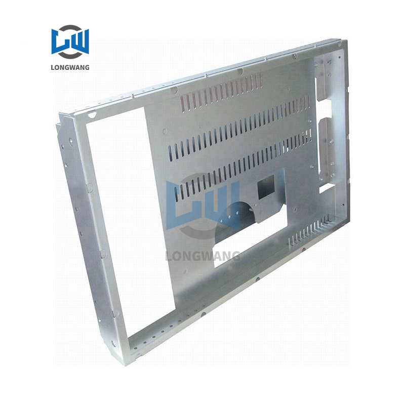
When geometry exceeds the physical limits of a press brake, joining becomes mandatory. A welded sheet metal assembly offers unparalleled design flexibility. It allows engineers to construct complex, multi-faceted structures that would otherwise require expensive castings or heavy hog-outs from billet material.
It is a counter-intuitive reality that a welded assembly can be more accurate than a single formed part. Welding simpler, precisely cut flat parts in a rigid fixture mitigates the tolerance stack-up inherent in multiple press brake operations. Laser cutting routinely holds tolerances of plus or minus 0.002 inches. By cutting individual flat plates and locking them into a precision-machined fixture, you establish exact datum points before any joining occurs. The fixture holds the critical dimensions rigid. The welder simply joins the intersecting seams. This approach bypasses bend-deduction errors and springback variables entirely.
Welding unlocks geometries that forming cannot achieve. You can easily combine different material thicknesses within the same assembly. A heavy-gauge base plate can be welded to thin-gauge housing walls to save weight. Enclosed profiles, such as custom rectangular tubing or complex ducting, require welding to close the final seam. Internal features, like stiffening ribs or mounting bosses, can be placed precisely inside a chassis before the outer skins are attached. This modular approach allows for internal access during fabrication that a single formed box would block.
Smart CAD design drastically reduces assembly costs. You should utilize self-locating design features. Tab-and-slot geometry is the most effective DFM tactic for sheet metal. You design interlocking tabs on one part that mate with laser-cut slots on the adjoining part. This creates a self-fixturing assembly. It drastically reduces the need for expensive custom fixturing. The parts only fit together one way, eliminating assembly errors. You should design a clearance of 0.005 to 0.010 inches between the tab and the slot to allow for easy insertion while maintaining rigidity. This accelerates assembly time and ensures squareness before the first tack weld is placed.
Welding introduces extreme localized heat. This thermal input alters the material and introduces significant manufacturing risks that must be managed through strict process control.
The primary enemy of sheet metal welding is thermal distortion. As the weld puddle cools, it contracts. This contraction pulls on the surrounding metal. On thinner gauges, this results in severe warpage, bowing, and twisting. A perfectly square assembly can turn into a twisted pretzel if welded improperly. Stainless steel is particularly susceptible due to its high coefficient of thermal expansion and low thermal conductivity. Heat distortion ruins dimensional accuracy and creates massive rework costs.
You must actively manage heat input. Stitch welding is highly effective. Instead of running a continuous bead, the welder places short, spaced-out welds. This limits total heat accumulation. Heat sinks, such as copper backing bars, draw thermal energy away from the joint. Strict weld sequencing is mandatory. Welders must alternate sides and balance the contraction forces. Post-weld stress relief, either through thermal annealing or vibratory methods, helps stabilize the assembly before final machining. Proper fixture design also restrains the parts during the cooling cycle, forcing the metal to yield rather than warp.
Choosing between these methods requires a direct comparison across multiple engineering and economic vectors. You must weigh upfront investment against recurring labor, and structural needs against cosmetic requirements.
The economic crossover point dictates the manufacturing strategy. Welding carries high manual labor costs. Skilled welders command premium wages, and the process is inherently slow. However, welding requires minimal upfront tooling. This makes it highly cost-effective for prototypes and low-volume runs. Complex forming requires expensive custom punches, dies, and lengthy setup times. The upfront cost is high. Yet, once running, the labor cost per part is minimal. High-volume production always favors forming. You must calculate the exact break-even quantity where the amortized tooling cost of forming drops below the recurring labor cost of welding.
The final application dictates the physical requirements of the part. You must map the manufacturing method to the desired outcome.
Cosmetic requirements heavily influence the decision. A continuous bent edge is immediately finish-ready. It requires zero secondary processing before powder coating or anodizing. Welded seams require extensive labor. If a smooth, seamless appearance is required, the welds must be ground flush, sanded, and polished. This grinding process often takes longer than the welding itself. Furthermore, microscopic pinholes in welds can trap cleaning chemicals, leading to outgassing and bubbling during the powder coat curing process. Forming provides a vastly superior out-of-the-box aesthetic.
Environmental sealing is another factor. A solid formed corner is inherently leak-proof. There is no path for liquid or gas to escape. Achieving a perfect seal with welding requires a continuous, defect-free bead. Even a microscopic pinhole will fail a pressure test or compromise a NEMA enclosure rating. While continuous welds can achieve liquid and gas containment, they require stringent quality control, dye penetrant testing, or pressure testing to verify. Forming eliminates this risk entirely on the bent edges.
The most efficient designs often utilize a combination of both methods. You do not have to choose strictly one or the other. A common hybrid approach involves forming the primary chassis to maximize structural integrity and minimize seam welding. You then weld secondary brackets, mounting points, or complex internal dividers into the formed shell. This optimizes cost by reducing total weld length while still accommodating geometric complexity. It leverages the speed of the press brake for the main body and the flexibility of welding for the intricate details.
Evaluation Criteria | Formed Sheet Metal Parts | Welded Sheet Metal Assembly |
|---|---|---|
Structural Integrity | Superior. Continuous grain, no heat-affected zones. | Variable. Depends on weld quality; introduces HAZ weak points. |
Dimensional Accuracy | Prone to tolerance stack-up across multiple bends. | High precision possible with rigid fixturing and laser-cut parts. |
Production Volume | Ideal for high volume. Low unit cost, high tooling cost. | Ideal for low volume/prototypes. High unit cost, low tooling cost. |
Geometric Complexity | Limited by press brake clearances and tonnage. | Unlimited. Can combine thicknesses and enclosed profiles. |
Aesthetics & Finish | Excellent. Clean edges, immediately ready for coating. | Labor-intensive. Requires grinding and polishing for smooth finish. |
Material Gauge | Forming Behavior | Welding Behavior |
|---|---|---|
20 to 24 Gauge (Thin) | Forms easily with low tonnage. Minimal springback. | High risk of burn-through and severe heat distortion. |
14 to 18 Gauge (Medium) | Excellent balance of strength and formability. | Ideal for TIG/MIG welding. Manageable distortion. |
10 Gauge to 1/4" (Thick) | Requires high tonnage. Watch for outer-fiber cracking. | Excellent weld penetration. Minimal warpage issues. |
Transitioning from a CAD model to a physical part requires understanding shop-floor realities. How you structure your data directly impacts the fabricator's ability to produce the component accurately and efficiently.
Drafting realities dictate manufacturing success. You must structure your CAD files from the fabrication shop's perspective. The strict necessity is modeling individual pieces of sheet metal as separate CAD part files. Do not design single multi-body weldments if you can avoid it. Fabricators need individual part files to generate accurate flat patterns. These flat patterns are fed into CAM software for efficient laser cutting nesting. Sheet metal assembly parts must be brought together in a master assembly file. This master file details the weld specifications, bill of materials (BOM), and overall dimensions. Improper CAD structuring forces the fabricator to manually separate bodies, increasing engineering time and the risk of translation errors.
You must also account for the K-factor and bend deductions specific to your fabricator's tooling. A flat pattern generated with a generic K-factor will yield incorrect final dimensions once bent. Communicate with the shop floor to obtain their specific tooling parameters before finalizing the flat patterns.
Welding is not always the correct joining method. You must evaluate when an assembly should actually be bolted or riveted. Vibration resistance is a key factor. In high-vibration environments, structural rivets like Huck bolts often outperform rigid welds, which can crack under cyclic fatigue. Maintenance accessibility demands mechanical fasteners. If internal components require future servicing, welding seals the enclosure permanently. Finishing sequencing also dictates fastening. If parts must be pre-painted or anodized before assembly, welding will destroy the finish. Finally, joining dissimilar metals, such as aluminum to steel, requires mechanical fastening or specialized adhesives, as standard arc welding is not viable.
The decision between forming and welding shapes the entire manufacturing lifecycle of your product. Formed sheet metal parts win on raw strength, finish-readiness, and high-volume unit cost. They provide a continuous material structure that is highly reliable. Welded assemblies win on geometric complexity, low-volume agility, and fixtured precision. They allow engineers to bypass the physical limitations of press brake machinery.
Take the following next steps to optimize your sheet metal designs:
Export all multi-body sheet metal designs into individual flat pattern DXF files to streamline laser nesting.
Integrate tab-and-slot locating features into your next weldment to eliminate the need for custom alignment fixtures.
Audit existing multi-bend components for tolerance stack-up and convert them to fixtured weldments if reject rates exceed acceptable limits.
Specify exact weld lengths and pitches on your manufacturing drawings instead of relying on generic continuous weld symbols.
A: Generally, yes. Formed parts maintain a continuous material grain and avoid the heat-affected zones (HAZ) that can introduce weak points, porosity, or brittleness in welded joints. A continuous bend distributes stress evenly, whereas a weld seam can become a failure point under dynamic or shear loads.
A: Every bend in a formed part carries a slight tolerance variation. In parts with multiple bends, these variations stack up. Welding simpler parts in a precision fixture locks in the exact final dimensions, bypassing bend tolerance stack-up completely. The fixture dictates the accuracy, not the press brake.
A: Welding is labor-intensive but requires minimal custom tooling, making it cost-effective for prototypes and low volumes. Complex forming requires expensive tooling and setup but offers a much lower per-unit cost at high volumes due to rapid cycle times.
A: The primary risks are heat distortion (warpage) and burn-through, especially on thin gauges. These are mitigated through proper fixture design, self-locating CAD features, stitch welding, heat sinks, strict weld sequencing, and utilizing skilled labor.
A: Industry best practice is to model every individual piece of sheet metal as its own unique part file to generate accurate flat patterns for laser nesting. Then, bring them together in a master assembly file to detail the weld specifications and bill of materials.
A: Bolting or riveting is preferred when joining dissimilar metals, when the assembly requires future maintenance or disassembly, when parts are pre-finished with powder coat or anodizing, or when the material is too thin to weld without severe thermal distortion.


